
Example Technical Drawing for a Laser-Cut and Bent Sheet Metal Part
Download the sample drawing as a PDF file
Technical drawings are used to manufacture a part correctly and to verify important production information such as bend dimensions, hole positions, and special requirements during manufacturing.

What the Example Shows
1. Bend Dimensions
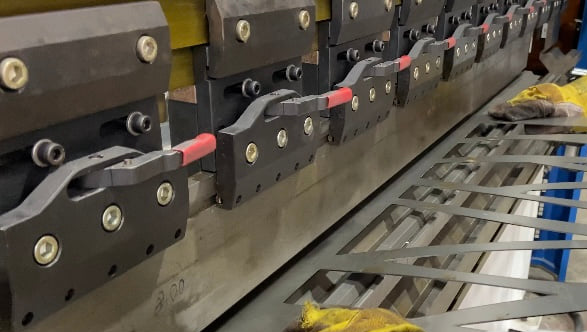
For bent parts, all relevant bend dimensions must be specified so they can be checked during press brake bending. Make sure all bend lengths, non-90 degree angles, and the corresponding bend radii are shown and dimensioned clearly.
2. Projection Method Information
Parts are normally shown in three-view projection. The source example uses the European projection method. This makes it clear how the views are derived from the main view. If a different projection method is used, the source warns that correct production according to the drawing may not be guaranteed unless the method is clearly indicated.
3. Countersink Drawing Information
If countersinks are to be produced later, only the core circles of the holes should be present in the vector DXF file. The countersink information itself should be given in the technical drawing.
4. Thread Drawing Information
If threaded holes are required, specify the thread size and position in the drawing. In the vector DXF file, only the core-hole circles for the threads should be present. The source notes that standard threads are produced according to ISO 742 / DIN 13-1.
5. Visible Side / Foil Side Information
If you want to order foil-coated sheet or you have a preferred visible side, indicate from which side the component should be processed if that was not already selected during upload. When cutting from the attached 2D vector file, the top view is treated as the selected side by default.
6. Laser Start Point Information (Optional)
Depending on the part size and production options, a micro-bridge may be placed at the laser start point to prevent the component from tipping. If you have specific design requirements for where laser cutting should start, mark that position in the drawing and mention it in the comment field. This can be useful if you want to avoid small surface marks at a specific point that could affect assembly behavior with other parts.

.png)

.png)
